Research Grade Instruments

Higher End Instruments

Abbe’s Refractometer

Features:

  • The Body of the Instrument is fixed, with a leaning of 600
  • It Consists of Abbe’s Double Prisms which leaves a narrow space (approx. 0.1 mm) between the adjoining faces of the prisms with the Thermostat, Compensator which consists of the amici prisms which serve for reading the line of Ach. Separation, Telescope Mirror, Limbs, Graduated Sector, Reading Magnifier and Radical arm which carries a vernier
  • Correct Refractive index and Sugar Percentage can be read directly in the field
  • Measuring Range of Refractive Index: ND 1.3000 to 1.7000
  • Measuring Accuracy: ± 0.001 by Direct Reading, ± 0.0001 by Estimation
  • Sugar % in Solution: 0 to 95% (± 0.5%)

Research Polarimeter – Half Shade

Features:

  • Sensitive rotating half shade device
  • Having angular and sugar scale from 00 to 3600 and +1300 to -1300S.S. sub divided in to 0.10 micro-meter drum enable to read up to 0.050 by estimate workable to use with Polarimeter tube 200 mm
  • Analyser: Glans Thompson Prism
  • Arrangement for 35 W Sodium lamp light Source, input 220 V ± 10% VAC
  • Borosilicate Glass Tube 200 mm
  • Plywood Storage Cabinet
  • Supplied with Instruction Manual & Dust Cover

Babinet Compensator

Features:

  • The instrument consists of two – round scales, one with index and the other with vernier
  • The first scale (index scale) is for tuning the analyzer into the azimuth.
  • The Second scale (Vernier Scale) is for measuring the degree of orientation of a wedge box.
  • The Wedge Box contains two wedges cut in the mutually perpendicular direction of the optics axis in quartz. The long wedge is movable by means of a micrometer drum, with the help of which accurate reading of the movement is taken.
  • Micro-meter screw minimum reading 0.001cm. (I.e. Least count)

Laser Spectrometer

Setup Supplied with the following:

  • Advance Deluxe Spectrometer 7”
  • In the said spectrometer, we have made arrangement for Diode laser & detector instead of telescope & collimator.
  • The diode laser is held in support rigidly & in perfect alignment at the place of a collimator. Similarly, output detector is held in support rigidly & in perfect alignment at the place of the telescope.
  • Vertical adjusting screws to align the diode laser & detector.
  • Supplied with grating holder, grating and diode laser with power supply and output detector with the digital meter.
reacherch-6

Michelson Interferometer

Features:

  • It is divided into two parts- (1) Mechanical (2) Optical
  • The mechanical part consists of following items
    • Bed: Bed is optically ground, Length 250mm
    • Lead Screw: Lead screw is optically ground with its nut, length 200 mm Pitch 1 mm
    • Optical Mirror Mount: Kinematic mirror mounts are to hold the mirror which is aligned into the Orthogonal direction by means of screws provided at the rare of the mount.
  • Optical Parts consist of the following items:
    • Beam Splitter Size: 45mm× 32mm × 8mm
    • Compensating plate Size: 50mm× 35mm × 8mm
  • The beam splitter and compensating plates are covered from the same optically worked glass plate
Surface Flatness λ/10 (both faces)
Parallelism 5 arcsec.
Mirrors 2 Nos.
Focal Length 25mm thickness 10mm
Front surface Coated Coating material: AI with SiO2
L.C. of Instrument 10¯4mm
  • Collimating Tube: (Material: Brass Pipe) O.D.: 50mm I.D.: 44mm for fitting collimating lens. It is provided with rack & pinion arrangement and slit. Slit is of circular type. The jaws of the slit are optically ground. It is provided with Holfmann’s Diaphragm.

Constant Deviation Spectrograph (C.D.S.)

Features:

  • Telescope Tube: (Material: Brass Pipe) O.D.: 50mm, I.D.: 44mm for fitting telescope lens. It is provided with rack & pinion arrangement for proper focusing of spectral lines. Eyepiece: (Ramsden Type): Magnification: 10x. In eyepiece holder, a conical pointer is fitted in the focal plane of the eyepiece
  • The corrected achromatic doublet is fitted in the lens holders of collimator and telescope tube. Doublet dia.: 44mm, F.L.: 350mm (14″). The Collimator and telescope tubes are fitted in cast iron blocks which are mounted on machined cast iron blocks which in turn are mounted on a machined cast iron plate.
  • The suitable gap is provided between the collimating lens and prism table to accommodate high resolving instrument like Fabry-Perot Etalon.
  • Prism Table is fitted on the machined cast iron plate and actuated by a tangent screw to provide smooth rotation of the C.D.S. prism placed on it.
  • Prism table is covered with a box of an aluminum casting having two gates. One gate allows light coming from the collimator to enter into C.D.S. Prism and another gate allows light to be collected by telescopic objective after light being dispersed from C.D.S. prism.
  • A calibrated drum (Calibration for visible region i.e. from 4000A°- 7000A°) is attached with the prism table assembly.
  • The accuracy of calibration + 5A°
  • Machined cast iron plate with drum assembly is fitted over the head of a heavy cast iron base.
  • The base and machined cast iron plate are painted in a staple Grey color.
  • Collimators, Telescope, Prism table, Drum assembly are painted black.
  • Total Weight: 20Kg.

X-Ray Diffraction Simulation Experiment (XDE-01)

Object: Identification of Lattice and Determination of Lattice Constant by X-Ray Diffraction Simulation

Setup Consist of the Following::

  • A battery operated laser mounted on a stand is put at one end of an optical bench.
  • The slide is mounted on another stand (Figure 1) which is kept at about 10-20 cm away from the laser such that the laser light falls normally on the slide.
  • The slide on this stand can be moved sideways and vertically so that the laser light falls on different portions of the slide.
  • The diffraction pattern is observed on a Perspex screen fixed normal to the laser light at the other end of the optical bench.

Dielectric Constant of Solids & Liquids (DSL-01)

A Cylindrical capacitor has been used for liquid samples and different size parallel plate capacitor for solid samples.

Setup Supplied with the following:

  • Probe Arrangement: Three probe arrangements are provided
    For solids two different size arrangements are given, one of 10 mm sample pellets and the other for 50 mm sample pellets and for liquids a separate arrangement is provided consisting of two polished brass cylinders fixed coaxially with insulating gaskets at the two ends
  • Samples: Glass, Bakelite, Barium Titanate, Lead Titanate, Carbon Tetrachloride Liquid
  • Digital Capacitance Meter: Microcontroller Based High-Resolution Instrument
  • Range: 0 pf – 50 nf with Resolution of 0.01 pf
  • Display: 16×2 LCD Display with backlight with accuracy better than 1%

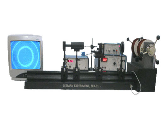
Zeeman Effect Setup (ZEX-01)

Setup Supplied with the following:

  • High Resolution Fabry Perot Etalon
  • Mercury Discharge Tube, (Low Pressure Mercury Discharge Tube)
  • High Voltage Power Supply for Mercury Discharge Tube
  • Narrow Band Interference Filter
    • Central Wave Length: 546nm
    • Tmax: 74%
    • HBW: 8nm
  • Polarizer with lens
  • Optical Bench
  • CCD Camera: CCD-01 (High Resolution CCD Camera)
  • Telescope with Focussing Lens
  • Monitor 14”
  • Electromagnet, EMU-50T
  • Constant Current Power Supply, DPS-50
  • Digital Gauss meter, DGM-102
  • A power pack to supply continuously variable voltage in the range 0 – 800 V to the upper plate electrode when the electric field is to be created between the plates. The lower plate is permanently grounded.

Millikan’s Oil Drop Experiment, MOD-01 (LED TV)

Setup Supplied with the following:

  • An oil drop chamber mounted on top of the panel. It has
    • A pair of horizontal parallel plate electrodes separated by about 5 mm thick ebonite ring with a hole for viewing the oil droplets.
    • The upper plate has a small hole in its center for the admission of the droplets which are produced by spraying oil with an atomizer.
    • A device to illuminate the space between the plate electrodes.
  • Three leveling screws at the base of the panel to make the parallel plate electrodes perfectly horizontal (perpendicular to the gravitational field) and a water-level placed on top of the panel to check it.
  • A microscope with CCD camera heads to view and transmit the image of oil droplets between the plate electrodes to the monitor.
  • A digital voltmeter to measure the potential applied to the upper plate.
  • A ‘Time Meter’ to display the time for which the oil droplet is allowed to move.
  • A timing device to measure the time interval between the passage of droplets through pre-set points between the plate electrodes. There are two keys to operate this device. Pressing the ‘Clear’ key, wipes out the time information. This is like a reset key. The time meter now reads ‘00.0’ sec. pressing the ‘Start/Stop’ key starts the timing device. Pressing it again stops the device. The elapsed time can be read on the meter.
  • A monitor with the graduated screen. The horizontal lines on the monitor screen help in setting the distance through which the droplets move.
  • An atomizer to spray droplets.
  • A thermometer to measure the room temperature.